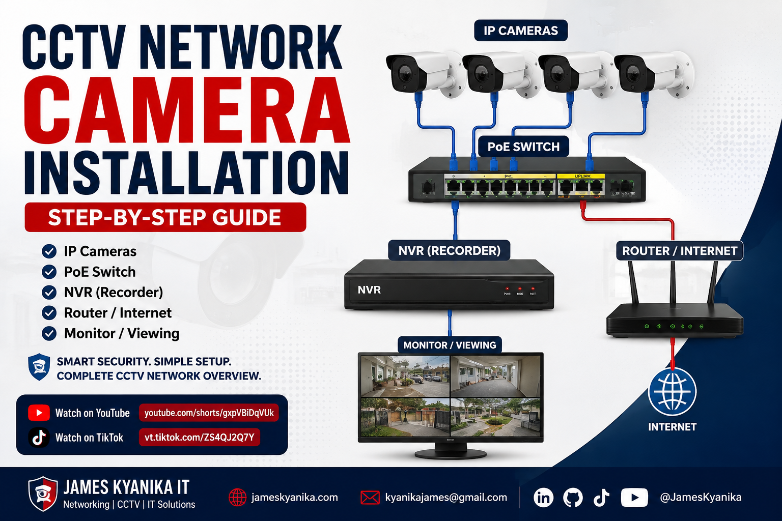
A CCTV network camera installation uses Internet Protocol cameras, commonly called IP cameras, to transmit video through an Ethernet network. Unlike traditional analogue CCTV systems, network cameras communicate using IP addresses and can receive both power and data through one Ethernet cable when connected to a Power over Ethernet switch.
This guide explains the basic equipment, cabling, configuration and testing process required to install a CCTV network camera system using IP cameras, a PoE switch, Network Video Recorder, router and monitor.
The exact menus and configuration options may vary depending on the camera and NVR brand. However, the installation principles described in this guide apply to most standard IP CCTV systems.
Equipment Required for the Installation
Before starting the installation, confirm that all the necessary equipment is available.
You will normally need:
- IP network cameras
- Network Video Recorder
- Surveillance-rated hard disk
- PoE network switch
- Internet router
- Cat5e or Cat6 Ethernet cable
- RJ45 connectors
- Network crimping tool
- Network cable tester
- Monitor or television
- HDMI or VGA cable
- USB mouse
- NVR power adapter
- Router power adapter
- Camera mounting screws and brackets
- Drill and suitable drill bits
- Cable clips, trunking or conduit
- Uninterruptible Power Supply where possible
The PoE switch must provide enough power for all connected cameras. Check its total PoE power budget and compare it with the power requirements of the cameras.
For example, if each camera requires 8 watts and four cameras are installed, the switch should provide more than 32 watts of available PoE power.
Understand the Basic Network Layout
The standard connection flow is:
- Each IP camera connects to a PoE port on the PoE switch.
- The PoE switch supplies power and network data to the cameras.
- The switch connects to the NVR network port.
- The switch or NVR connects to the router.
- The NVR connects to the monitor using HDMI or VGA.
- A USB mouse connects to the NVR for configuration.
- The router provides local network access and internet connectivity for remote viewing.
The router is not always required for local recording and viewing. However, it is normally required when users need mobile-phone access, remote monitoring, time synchronization or firmware updates.
Step 1: Plan the Camera Locations
Start by inspecting the premises and identifying the areas that require monitoring.
Common camera locations include:
- Main entrances and exits
- Reception areas
- Corridors
- Parking areas
- Cash-handling points
- Store rooms
- Server rooms
- Gates and perimeter walls
- Loading and delivery areas
Avoid installing cameras directly toward strong sunlight, bright security lights or reflective surfaces. These conditions can reduce image quality.
The camera should be high enough to reduce tampering but positioned low enough to capture useful facial and activity details.
Before drilling, confirm:
- The camera has a clear field of view.
- There are no permanent obstructions.
- The cable route is accessible.
- The camera is protected from rain if it is not weatherproof.
- Night-vision infrared light will not reflect from nearby walls or glass.
- The total cable length will remain within Ethernet distance limits.
A single Ethernet cable run should normally remain below 100 metres. Longer distances may require a network switch, PoE extender or fibre connection.
Step 2: Install the Surveillance Hard Disk in the NVR
Many NVRs are sold without a hard disk. The hard disk must be installed before the recorder can store video.
Switch off and disconnect the NVR before opening it.
The general process is:
- Remove the NVR cover.
- Place the surveillance hard disk inside the recorder.
- Secure it with the provided screws.
- Connect the SATA data cable.
- Connect the SATA power cable.
- Confirm that the connectors are firmly seated.
- Replace the NVR cover.
Use a surveillance-rated hard disk designed for continuous recording. Ordinary desktop drives may not be suitable for constant video-writing workloads.
After powering on the NVR, the disk may need to be initialized or formatted from the storage settings menu. Formatting deletes any existing information on the drive.
Step 3: Run and Terminate the Ethernet Cables
Run one Ethernet cable from the PoE switch location to each camera.
Use Cat5e or Cat6 cable from a reliable manufacturer. For outdoor installations, use outdoor-rated cable or protect the cable inside conduit.
Avoid running Ethernet cable directly beside high-voltage power cables because electrical interference may affect communication.
Terminate both ends using RJ45 connectors and the same wiring standard. The commonly used standard is T568B.
The T568B colour sequence is:
- White-orange
- Orange
- White-green
- Blue
- White-blue
- Green
- White-brown
- Brown
After crimping each connector, test the cable using a network cable tester.
The tester should confirm that pins 1 to 8 are correctly connected and in the proper order.
Label both ends of every cable. For example:
- Camera 1 – Main Entrance
- Camera 2 – Reception
- Camera 3 – Parking Area
- Camera 4 – Store Room
Good labelling makes future troubleshooting much easier.
Step 4: Mount and Connect the IP Cameras
Fix each camera to the planned location using suitable screws and mounting plugs.
Before final tightening:
- Point the camera toward the required area.
- Confirm that its field of view is not blocked.
- Connect the Ethernet cable to the camera.
- Protect outdoor connections using a weatherproof junction box.
- Avoid leaving exposed connectors where rain can enter.
Connect the other end of each camera cable to a PoE-enabled port on the switch.
The PoE switch should automatically supply power to the camera. Camera power or network indicators may illuminate after a few seconds.
If the camera does not power on, confirm that:
- The switch port supports PoE.
- The cable is correctly terminated.
- The cable length is not excessive.
- The camera is compatible with the switch’s PoE standard.
- The switch has enough available PoE power.
Step 5: Connect the PoE Switch, NVR and Router
Use a short Ethernet patch cable to connect the PoE switch uplink port to the local network.
Depending on the design, connect the uplink to either:
- The router or main LAN switch, or
- The NVR network port
When the cameras, NVR and router are connected through the same switch or network, they should be able to communicate within the same IP subnet.
A typical example might be:
- Router:
192.168.1.1 - NVR:
192.168.1.10 - Camera 1:
192.168.1.101 - Camera 2:
192.168.1.102 - Camera 3:
192.168.1.103
These addresses are only examples. Use the addressing structure provided by the router or network administrator.
Every device must have a unique IP address. Duplicate addresses can cause cameras to disconnect or appear offline.
Step 6: Connect the Monitor and Mouse
Connect the NVR to a monitor or television using an HDMI cable. VGA may also be used when HDMI is unavailable.
Connect a USB mouse to one of the NVR’s USB ports.
Then connect the NVR power adapter and switch on the system.
During the first startup, the NVR may ask you to:
- Select the language
- Set the country or region
- Create an administrator password
- Configure the date and time
- Select the time zone
- Configure the network
- Initialize the hard disk
- Set security questions or recovery options
Create a strong administrator password and store it securely. Do not leave the NVR using a default password.
Step 7: Configure the NVR Network Settings
Open the NVR network settings.
In many installations, the NVR can initially obtain an address automatically from the router using DHCP.
After confirming that the system is working, it is normally better to assign the NVR a fixed address. This can be done using either:
- A static IP address configured on the NVR, or
- A DHCP reservation configured on the router
Record the following details:
- NVR IP address
- Subnet mask
- Default gateway
- DNS server
- HTTP or management port where applicable
The default gateway should normally be the router’s IP address.
Correct DNS and gateway settings are required for remote services, cloud registration, email notifications and time synchronization.
Step 8: Discover and Add the Cameras
Open the camera-management or device-search section of the NVR.
The NVR should scan the local network and display available cameras.
Select each camera and add it to the recorder.
The system may request:
- Camera IP address
- Camera username
- Camera password
- Protocol
- Port number
Many cameras support ONVIF, which allows cameras and recorders from different manufacturers to communicate. However, some advanced functions may work better when the NVR and cameras are from the same manufacturer.
After adding the cameras, confirm that each channel displays:
- Online status
- Live video
- Correct camera name
- Correct date and time
- Stable image quality
Rename each channel according to its location instead of leaving generic names such as Camera 1 or Channel 1.
For example:
- Main Entrance
- Reception
- Parking
- Store Room
Step 9: Configure Recording
Open the NVR recording or schedule menu.
Common recording options include:
- Continuous recording
- Motion-detection recording
- Event recording
- Scheduled recording
- Manual recording
Continuous recording provides complete coverage but consumes more storage.
Motion recording saves storage, but it must be configured carefully. Incorrect sensitivity settings may cause missed events or excessive recording.
For important locations such as entrances or cash-handling points, continuous recording may be more suitable.
Confirm that the correct camera channels are selected and that the recording schedule covers the required days and hours.
After configuration, perform a playback test. Record a short activity, wait a few minutes, and confirm that it can be found in the playback menu.
Step 10: Configure Video Quality and Storage
Select suitable resolution, frame rate and compression settings.
Higher video quality provides more image detail but uses more network bandwidth and storage.
Common options may include:
- Resolution
- Frames per second
- Main stream
- Sub-stream
- Bitrate
- H.264 or H.265 compression
- Constant or variable bitrate
The main stream is normally used for recording, while the sub-stream is often used for mobile viewing.
H.265 can reduce storage consumption when supported by both the cameras and NVR.
Storage duration depends on:
- Number of cameras
- Camera resolution
- Frame rate
- Bitrate
- Recording schedule
- Motion activity
- Compression type
- Hard-disk capacity
After configuring these settings, check the NVR’s estimated retention period.
Step 11: Configure Remote Mobile Viewing
Most modern NVR systems provide a mobile application or cloud platform.
The exact application depends on the manufacturer.
The general process is:
- Connect the NVR and router to the internet.
- Open the NVR platform-access or cloud settings.
- Enable the remote-access service.
- Confirm that the status changes to online.
- Install the manufacturer’s application on the phone.
- Create or sign in to the required account.
- Scan the NVR QR code or enter its serial number.
- Add the device.
- Confirm live viewing and playback.
Use a strong account password and enable two-factor authentication when the platform supports it.
Avoid exposing NVR management ports directly to the internet unless there is a clear technical requirement and appropriate security controls.
Step 12: Test the Complete Installation
After all cameras are added, perform a complete system test.
Confirm the following:
- Every camera displays live video.
- All camera names are correct.
- Date and time are synchronized.
- Night vision works in low-light conditions.
- Motion detection works where required.
- Recording is active.
- Recorded video can be played back.
- The hard disk has no errors.
- Remote viewing works.
- Cameras reconnect after restarting the system.
- Cables and connectors are secure.
- The NVR is protected by a strong password.
Walk through each monitored area and confirm that important details are visible.
Check whether faces, vehicle movement, entrances and other key activities can be identified clearly.
Common CCTV Network Camera Problems
Camera Shows Offline
Check:
- Camera power
- PoE switch port
- Ethernet cable
- RJ45 termination
- Camera IP address
- Camera password
- NVR protocol
- Network subnet
Test the camera using another PoE port and a known working cable.
Duplicate IP Address
Two devices using the same IP address may disconnect or behave unpredictably.
Assign every camera and the NVR a unique address.
Camera Powers On but Has No Video
Confirm that the camera has been added using the correct username, password and protocol.
Also confirm that the selected video format is supported by the NVR.
Remote Viewing Does Not Work
Check:
- Internet connection
- NVR gateway
- DNS settings
- Cloud-platform status
- Router firewall
- Mobile application permissions
The NVR should normally show an online status before remote viewing can work.
No Recording or Playback
Check:
- Hard-disk status
- Recording schedule
- Camera selection
- Available storage
- Disk initialization
- Event settings
A camera may display live video while recording remains disabled.
Security Recommendations
A CCTV system is part of the organization’s network and should be secured appropriately.
Apply these basic controls:
- Change all default passwords.
- Use different passwords for the NVR and cameras where possible.
- Keep device firmware updated.
- Disable unused services.
- Restrict administrative access.
- Use a dedicated CCTV VLAN where practical.
- Back up important configuration information.
- Protect the NVR and network equipment with a UPS.
- Review user accounts regularly.
- Avoid sharing administrator credentials.
- Confirm remote-access settings periodically.
For business environments, CCTV traffic can be isolated from the main office network using VLANs and firewall policies.
Watch the CCTV Network Setup Video
The short demonstration below shows the equipment layout and connection flow used for this CCTV network camera installation.
Watch on YouTube
CCTV Network Camera Installation – YouTube Short
Watch on TikTok
CCTV Network Camera Installation – TikTok Video
Conclusion
A successful CCTV network camera installation depends on proper planning, reliable cabling, correct IP addressing, secure configuration and complete testing.
The cameras connect to the PoE switch, the switch provides power and network communication, the NVR records the footage, the monitor displays the video, and the router enables network and remote access.
Document the final camera locations, IP addresses, passwords, cable labels and system settings. Good documentation reduces troubleshooting time and makes future maintenance easier.
This installation guide provides a general process that can be adapted to different NVR and IP-camera brands. Always consult the manufacturer’s manual for brand-specific menus, supported protocols and security requirements.